
But this is clearly one of the most incredible vehicle ever built... And it's Russian.
Monday, 29 December 2008
Thursday, 25 December 2008
Théo Jansen, The Hague, Netherlands, Born 1948.

"The walls between art and engineering exist only in our minds."

Inspiring, innovative, mindblowing...


http://www.strandbeest.com
http://www.strandbeestmovie.com/
http://www.cove.org/ape/demo2.htm
Wednesday, 24 December 2008
Drive Time history

During the last years, we received many emails about the re-releasing of Drive Time, an early root of Firstcask. By then we replied "take it easy you'll get your hands on it for sure". Though we didn't know when that would happen to be honest. As you may know, Drive Time has been first released as a bonus cassette for the "FSK005" album back in the year 2000. Considering the great enthousiasm that raised for both the album and the cassette we wanted to press this one on vinyl and having another bonus cassette next to it. Just to continue offering free stuff with our sales to have the pleasure to give pleasure or something... How comes it didn't happen straight away? Sure we messed up a bit on the schedule. But you know the score with belgian latin boys... You don't? Good! Then when we finally were ready, Andy came up with the second cassette, but distributors told us it wasn't that wise because cassette players disappeared from the market! I heard there is still that flee market round the corner though! You sure? Not handy and expensive to ship but there is some kind of poetry in this. Ok, fair enough, I'm also slave of a banker who has my balls in his palm and squeeze it from time to time a bit like how Chuck Norris does when strengthening his hands. Tough I recall that by the time we shipped our catalogue through lorries carrying vegetables across Europe. We even reached the japanese shore with the diplomatic wallet, and other remote areas thanks to backpackers or friends traveling around with a bunch of records in their bags. They simply were meeting people, having a shared meal while listening to the music and then selling the records. That brought us much satisfaction as we acheived to bring the music straight from the musician's fingers to the ears of any unknown happy ravers. It worked quite well at the time but was more than exhausting to maintain. Especially to collect money. Can you blame one of these wayfarers spending the benefits just made on buying that boat ticket to get out of Taiwan? Or for that slideshow for kids in Senegal were there is no screen but well a white horse to project on to "for not that much". Quite poetic indeed but the financial results remained at sea level. Still it is. And water is rising! But Weme records is there to give a hand. Cheers mate! Then together we are proud to bring you the brew which stayed for 10 years in the cask. This is half an image as the metalworks stayed untouched since 2003 at the pressingplant. We called them every two years to make sure they wouldn't chuck it in the bin. That would have been a shame because it took us multiple sessions and a few lacquers to cut this piece onto acetate. Nearly tirty minutes per side from sparkling water to deep bass. How to describe Drive Time other than being a wayfarer's anthem? First Cask wayfaring arose early 2000 when we first traveled together with Andy and Joy (Andy's girlfriend of the time who appears on the cover) from Hull to the North East of England. We went up to Whitby, where Dracula's coffin ashored. Not that far away from Robin Hood's bay if you're familiar with that beautiful region. We drove for hours by bus and taxi with litterally hundreds of Ceephax unreleased tracks (earliests from 1997 I think) while staring at tortured trees, windy landscapes, ruined abbays, english seagulls and english carpets... TBC
Optophonic piano, Wladimir Baranoff Rossiné, 1916, "L'avant-garde russe"

"Imagine that every key of an organ’s keyboard immobilises in a specific position, or moves a determined element, more or less rapidly, in a group of transparent filters which a beam of white light pierces, and this will give you an idea of the instrument Baranoff-Rossiné invented.

There are various kinds of luminous filters: simply coloured ones optical elements such as prisms, lenses or mirrors; filters containing graphic elements and, finally, filters with coloured shapes and defined outlines. If on the top of this, you can modify the projector’s position, the screen frame, the symmetry or asymmetry of the compositions and their movements and intensity; then, you will be able to reconstitute this optical piano that will play an infinite number of musical compositions. The key word here is interpret, because, for the time being, the aim is not to find a unique rendering of an existing musical composition for which the author did not foresee a version expressed by light. In music, as in any other artistic interpretation, one has to take into account elements such as the talent and sensitivity of the musician in order to fully understand the author’s mind-frame. The day when a composer will compose music using notes that remain to be determined in terms of music and light, the interpreter’s liberty will be curtailed, and that day, the artistic unity we were talking about will probably be closer to perfection..."

More at the Wladimir Baranoff Rossiné's website.
Tuesday, 23 December 2008
Seventy Years of Broadcasting in Belgium
By Richard E. Wood
This article was originally published in the August 1984 edition of FRENDX, now The Journal of the North American Shortwave Association. It appears here without permission of NASWA.
"Un, deux, trois, quatre .... díx. Allo, allo. Poste radiotélegraphique et radioteléphonique, pres de Bruxelles. Messieurs les amateurs de télégraphie sans fil, nous allons vous faire entendre un concert dédié á Sa Majesté la Reine Elisabeth... " The first selection was the aria from "Tosca" sung by a vocalist whose name is unintelligible in the primitive recording which survives.
More here.
Raymond Scott, New York, 1908-1994

"What can you say about a man who inspired cartoon melodies and bebop, invented Frank Zappa and electronic music, and still found time to work for-Motown?"
- Andy Partridge, songwriter & leader of XTC

"Raymond Scott was like an audio version of Andy Warhol; he preceded Pop-Art sensibilities, and he played with that line between commercial art and fine art, mixing elements of both worlds together. I love and respect Raymond Scott's work, and it influenced me a lot. I'm a big fan.''
- Mark Mothersbaugh, DEVO

"Raymond Scott's music gets better as it gets older. When it first appeared, it was so bizarre it could not be categorized. Now, it is no less innovative and comic, but it begins to occupy a serious role in our total music-appreciation."
- Dick Hyman, musician

In 1946 Raymond scott founded the Manhattan research inc., one of the very first studios of electronic music in the world.

He also created The Talking Alarm Clock and fascinating musical instruments like The Orchestra Machine, The Karloff, The Bassline Generator, The Circle Machine, The Clavivox , The Videola, The Rhythm Synthesizer, The Pitch Sequencer, The Juxtaposition Matrix, The Synthesized Gong, The Melody Maker, The Rhythm Guitar Simulator or The Electronium-Scott plus a large number of patents used by the musical industry. That's a boy!

There is numerous websites referencing his work and audio simples are fairly easy to find as well. Just take a plunge!

Saturday, 20 December 2008
RCA record manufacturing process 1942 part 1
Direct cut with a Scully lathe, straight onto wax... Beautiful...
Friday, 19 December 2008

Thursday, 18 December 2008
Lee De Forest, 1873-1961

American scientist,
Invents the Audion grid-triode vacuum tube in 1906 used as a detector of radio signals, an audio amplifier and an oscillator for transmitting.
De Forest is credited with the Birth of public radio broadcasting when on January 12, 1910, he conducted experimental broadcast of part of the live performance of Tosca and, the next day, a performance with the participation of the Italian tenor Enrico Caruso from the stage of Metropolitan Opera House in New York City.

Caruso, breaks hearts and glass with his voice, also haunting Werner Herzog's Fitzcarraldo.
I remember reading in that excellent book from Suzan J. Douglas that De Forest was a meloman but couldn't afford a seat at the opera. He was relentlessly placed behind a column. He then promised himself to use his telegraph apparatus to bring music in people's houses. By doing this, he changed the way wireless telecommunication was used, originally from point to point (eg warship to military base) to omnidirectional broadcast. Fairly good intentions there. Thank you sir!
Here is the book reference:
Suzan J. Douglas,
Inventing american broadcasting 1899 - 1922,
The John Hopkins University Press,
Paperback, Baltimore and London, 1987, 365p.
ISBN 0-8018-3832-0
Reginald Aubrey Fessenden, 1866-1932

American physicist, inventor,
Transmits human voice on radiowaves via high-frequency oscillator, December 23rd ,1900.
"One-two-three-four, is it snowing where you are Mr. Thiessen? If it is, would you telegraph back to me?"
Mr. Thiessen, one mile distant, confirmed. Such a luck it was snowing. Radio broadcasting was born.
More on the hammond museum of radio website.
Wednesday, 17 December 2008
Rahul Dev Burman

Last summer, Jamie turned up in Ostend as he was invited to participate to some flemish tv show. After some beers in town, we started to feel starvation then we went at mine with his agent and promoter for some night cooking action. Probably we talked crap for a bit but I remember we talked about India and Jamie said he was totally amazed by a couple of people playing on the roof of his hotel in order to welcome him and his band. It brought him much inspiration that he went to a music store down the street and asked for the craziest indian composer. He came back with R D Burman. We downwloaded some straight away and had a good laugh. It stayed in my player for weeks and I reckon mister Burman deserves to be known by everyone. It sounds like a curry of cha cha, country, exotica, espionage with a touch of musical comedy. All in once. How serious is that! You'll have to find your way in the thousands tracks he made though... Good luck!
Following a heart attack in 1988, R D Burman underwent a bypass surgery abroad the next year. While recuperating he is said to have composed over 2,000 tunes which he kept in his memory bank. He often said that his best tunes came to him in his dreams and that he had to be in happy frame of mind even while composing sad tunes. "When I am down, I end up making a mess of things," he is reported to have said.
Much much more on the interweb...
Plan 9 from Bell Labs
Plan 9 began in the late 1980’s as an attempt to have it both ways: to build a system that was centrally administered and cost-effective using cheap modern microcomputers as its computing elements. The idea was to build a time-sharing system out of workstations, but in a novel way. Different computers would handle different tasks: small, cheap machines in people’s offices would serve as terminals providing access to large, central, shared resources such as computing servers and file servers. For the central machines, the coming wave of shared-memory multiprocessors seemed obvious candidates. The philosophy is much like that of the Cambridge Distributed System [NeHe82]. The early catch phrase was to build a UNIX out of a lot of little systems, not a system out of a lot of little UNIXes.
Full info and download here.
Full info and download here.
Peter Zinovieff & EMS

It may be difficult for a generation brought up with 32-bit computers and digital signal processors as consumer items to appreciate just how revolutionary Peter Zinovieff's projects were. In the 1960s to have access to a 12-bit computer with 1K of memory outside the academic or military establishment, let alone have two personal ones and then use them for music, was completely unheard of. To have a video screen as well when most people programmed with punched cards was beyond belief. Today there is a huge worldwide market for electronic music equipment, but there is little that was not envisioned by the EMS team before 1970 ten to twenty years ahead of their time.
Full article here.
Tuesday, 16 December 2008
The Unit Delta Plus Studio

Unit Delta Plus was an organisation set up in 1966 by Delia Derbyshire, Brian Hodgson and Peter Zinovieff to create electronic music and also promote its use in television, film and advertising. The Unit Delta Plus studio was based in Peter Zinovieff's townhouse in Deodar Road, Putney, London.
More at: http://www.delia-derbyshire.org/unitdeltaplus.php

Bhutan Record stamps

These are postage stamps:
Some kind of a promotional thing… Maybe… Maybe not! You couldn't really play them as they were too small. From one and a half to three inch or so, any automatic turntable would lift up the arm… They are one sided and have five different recordings, some of them are musical.
Never heard of Bhutan before seeing this. Their promotion action must have been working in some way! If you have any audio link for this please let us know. We'll make sure to spin it on the next rave!
Anyway, here is where to get them: http://www.bhutanstamp.com
X-Ray Sound Recordings

In the USSR and Eastern Europe in the 1950s underground night spots would play music pirated from the west.
The only media they had were recorders etched into discarded X-ray film, the method became so widespread in Hungary that not only amateurs, but the Hungarian Radio made sound recordings on such recycled X-ray films.
from kevin kelly's: street use archives
Black noise and population persistence
Biological populations are susceptible to random variation in environmental influences such as temperature and moisture. This variability (or noise) can determine population size and, ultimately, cause extinctions. Extinction risk depends on noise colour or the amount of short- and long-term variation. Most environmental noise is reddened: the variation is dominated by long-term £uctuations. Recent modelling has shown that moderately reddened noise affects populations differently from the white noise used in earlier studies. However, some geophysical phenomena, such as temperature and river height, can have deeply reddened `brown' or even `black' spectra. We find that, compared to environments characterized by red noise, very long population persistence times are more likely for black noise. Unlike previous work incorporating a simple autoregressive model of reddened noise, our model suggests that the large variation associated with persistence in a red-noise environment limits our ability to predict the fate of particular populations subject to this noise colour. Thus, we identify the colour of noise experienced by a population - red or black - as a crucial factor in any attempt to manage or conserve that population.
Full article here.
Full article here.
From AC power hum to synesthesia
100/100: colored noise:
Name: Mark Thompson #9
Date: 1:00 pm Wed Dec 27, 1989
I work with colored noise occasionally, and recently made several tapes utilizing psychoacoustic noise effects.
Here's a rundown of some interesting varieties of "noise":
White Noise: This kind of noise has equal energy (loudness, or volume) over frequency -- that is, if you measure the amplitude of the sound from 100 to 200 Hz (Hz means "Hertz" or "cycles per second") that chunk of the frequency spectrum will have the same sound amplitude as a chunk from 3000 to 3100 Hz or even 20,000 to 20,100 Hz. White noise is kind of "bright" and not terribly relaxing, but is very effective for masking other sounds, and has been shown to promote auditory hallucinations under certain circumstances.
Pink Noise: This noise has equal energy PER OCTAVE. This means that the volume decreases logarithmically with frequency. Usually pink noise is made by low-pass filtering white noise. For comparison, pink noise will have the same sound amplitude
from 100-200Hz that it does from 200-400Hz or 10,000-20,000Hz. Pink noise sounds more natural than white noise (it sounds like rushing water or ocean surf) and is quite relaxing. It's often used for ambience in electronic music, and as a test signal for "tuning" sound reenforcement systems (many equalizers and audio spectrum analyzers have built-in pink noise generators).
Red Noise: A very bassy (heavily low-pass filtered) kind of noise. This sounds like a low rumble - a subway train going by or a noisy air-conditioning system. The definition of red noise is not as precise as that of white and pink noise, and the term mostly refers to low-pitched noises used for electonic music.
Brown Noise: This is a special kind of noise that has a 1/f amplitude distribution - the volume is inversely proportional to pitch. It has the special property of being a "fractal" or statistically self-similar waveform. No matter how far you zoom in on the wave with an oscilloscope, the waveform has the same "texture". Brown noise is also the sound made by a "random walk" which makes the amplitude of a waveform travel up and down at random. The pitch motion of most musical melodies have a 1/f distribution, which is more a measure of melodic texture than a commentary on the musical experience.
Blue Noise: This is just high-pass filtered white noise. It sounds really screechy and artificial. Like "Red Noise" this is not a precise term, and just refers to noises with a lot of treble tones.
Diotic Noise: This refers to the stereophonic or binaural properties of a noise signal. Diotic noise is the same noise signal presented to both ears - monaural noise. Diotic noise can be either in-phase or phase-reversed. In-phase noise sounds like it is coming from inside one's head when heard through headphones. 180-degree phase-reversed noise sounds like it is coming from "all around" one's head when heard through headphones.
Dichotic Noise: This is two separate, unrelated noise signals presented to each ear. It's much more stimulating and refreshing (subjectively) than monaural or diotic noise. Where monaural noise sounds like radio hiss, dichotic noise sounds like being outdoors in a rainstorm.
Taken from: http://mv.lycaeum.org/M2/noise_ahf.html
Others
There are also many "less official" colors, usually with multiple definitions
Red noise
1. A synonym for Brownian noise, as above
2. A synonym for pink noise, as above
Orange noise
"Orange noise is quasi-stationary noise with a finite power spectrum with a finite number of small bands of zero energy dispersed throughout a continuous spectrum. These bands of zero energy are centered about the frequencies of musical notes in whatever scale is of interest. Since all in-tune musical notes are eliminated, the remaining spectrum could be said to consist of sour, citrus, or "orange" notes."
Green noise
1. "Green noise is supposedly the background noise of the world. A really long term power spectrum averaged over several outdoor sites. Rather like pink noise with a hump added around 500 Hz."
2. The mid-frequency component of white noise, used in halftone dithering[12]
3. Bounded Brownian noise
Black noise
Black noise, or silent noise, has several different definitions:
1. Silence
2. Noise with a 1/fβ spectrum, where β > 2 (Manfred Schroeder, "Fractals, chaos, power laws"). Used in modeling various environmental processes. Is said to be a haracteristic of "natural and unnatural catastrophes like floods, droughts, bear markets, and various outrageous outages, such as those of electrical power." Further, "because of their black spectra, such disasters often come in clusters."
3. Noise that has a frequency spectrum of predominantly zero power level over all frequencies except for a few narrow bands or spikes. Note: An example of black noise in a facsimile transmission system is the spectrum that might be obtained when scanning a black area in which there are a few random white spots. Thus, in the time domain, a few random pulses occur while scanning.
4. "The output of an active noise control system which cancels an existing noise, leaving the local environment noise free. The comic book character Iron Man used to have a "black light beam" that could darken a room like this, and popular science fiction has a tendency to portray active noise control in this light."[11] The Batman Beyond supervillian Shriek also had a weapon like this, which effectively blocked out all noise.
5. "As seen in the sales literature for an ultrasonic vermin repeller, black noise with a power density that is constant for a finite frequency range above 20 kHz. More accurately, ultrasonic white noise. This black noise is like the so-called black light with frequencies too high to be sensed, but still capable of affecting the environment."
Noisy white
In telecommunication, the term noisy white has the following meanings:
1. In facsimile or display systems, such as television, a nonuniformity in the white area of the image, i.e., document or picture, caused by the presence of noise in the received signal.
2. A signal or signal level that is supposed to represent a white area on the object, but has a noise content sufficient to cause the creation of noticeable black spots on the display surface or record medium.
Noisy black
In telecommunication, the term noisy black has the following meanings:
1. In facsimile or display systems, such as television, a nonuniformity in the black area of the image, i.e., document or picture, caused by the presence of noise in the received signal.
2. A signal or signal level that is supposed to represent a black area on the object, but has a noise content sufficient to cause the creation of noticeable white spots on the display surface or record medium.
5 Places To Get Started With Chipmusic
The HVSC (as posted below) is only a tiny part of the surprisingly big network of genius musicians making tracks on lo-fi hardware and redundant soundchips - the modern 'chipscene' features some rocking trax, which if you dig techno/acid/electro/etc you're sure to like! Here are some places to get you started (a lot of it is free too, which is great!):
8bitpeoples - Best chipmusic label, all the greatest artists associated with chipmusic have released EPs here. Check out 'Power Supply' by Anamanaguchi for some hypermelodic NES-punk trax or 'Molen' by Gijs Gieskes for some glitchy Game Boy funk!
Retinascan - If you want to check out some great physical releases, Retinascan sell the output of plenty of ace labels and also some killer stuff of their own (check 'Atari Solo' by Stu for the most face-meltingly slamming piece of electro you'll ever hear being made on an Atari, released on a 3'' CD!).
Kittenrock - the UK's first chipmusic netlabel, everything from weird pop songs to their legendary 'Pornochip' release (has to be experienced to be believed), also check out Steve Nosurname's own release there...
8BitCollective - an overwhelming library of chipmusic and pictures, and the best forum for chipmusic on the web.
Micromusic - Some brilliant singles from just about everyone (including Cylob and EDMX!), and loads of info about making chipmusic (not to mention some very handy pages with links to freeware/etc). Once you've made some good chipmusic yourself, upload it here for the possibility of it being released on this hugely influential netlabel!
So...Check!!!
The High Voltage SID Collection (HVSC) Links Page
Commodore 64 music for the masses

One of the most accurate and complete resource page for SID files can be found here.

One of the most accurate and complete resource page for SID files can be found here.
XY interactive textile

The XY interactive textile is a large tactile interface for playing electronic music. The performer plays it simply by the movement of his/her hand on it's surface. This textile interface allows users to compose and interpret electronic music by choreographic movements. By its size, its texture, its flexibility and its transparency, this textile interface involves the whole body in the musical interpretation. Like a music score, the sound elements are graphically represented on the fabric, giving to the composer the ability to locate and play (with) them. Thus, for each piece of music, a graphic partition is carried out. The idea behind this project is also to develop an opposite approach to a classical process (from graphic towards the sound). Created in collaboration with graphic designers and composers, these hybrid textiles offer spaces to be explored by look, touch and gesture.
More info here.
Singing Arcs or Musical Tesla Coils

A few words about safety:
1. Burning steel produces some really nasty fumes. When mixed with Ozone and NO2 they will surely do you harm. Therefore ensure adequate ventillation and don't breath the fumes.
2. The plasma is hot ! If it starts steel burning in seconds, it will damage skin in milliseconds. Do not take an arc to the skin or any held object.
3. Hot metal particles are showered everywhere, and the screwdriver remains hot for some time after the power is cut. There is a real risk of setting fire to nearby objects or burning your skin. Give things plenty of time to cool before touching.
The hardware store where I got my screwdriver wouldn't honour the "lifetime guarantee" either ;-)
There are many ways of modulating a SSTC (solid state tesla coil), the 2 most popular being AM (amplitude modulation) and what i will call "PRF Modulation". PRF stands for pulse repitition frequency. The reason these 2 modulations exist, is because there are 2 (actually more) distinct types of SSTC. Those that can produce a continuous spark output (that is, a flame like plasma that exists at 100% duty cycle) and those that make what appear to be a continuous spark, but are rather producing sparks at several hundred times per second with a rest between each spark event. The first (continuous) type of SSTC lends itself to audio modulation. Normally the output spark is a silent plasma flame. By modulating the amount of power put into the plasma flame, we can modulate the physical volume of the plasma. Modulating the size of the plasma will cause the expansion/relaxation of air surrounding the plasma, thus producing sound waves.
Now go for it here!
Or go for Ward and Larson's twin Tesla coils!
Gladdening (being glad and that)
while floating around LA...
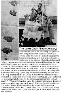
Here is where to get the balloons:
Make yourself familiar with knots and parachute design for a full enjoyment!!!
If everything goes wrong stretch your arms on the side and get ready for the burst.

Here is where to get the balloons:
Make yourself familiar with knots and parachute design for a full enjoyment!!!
If everything goes wrong stretch your arms on the side and get ready for the burst.
Record on a wire DIY

To do this project, you should do research that enables you to understand the following terms and concepts:
* transducer,
* Ohm's Law,
* magnetic coil,
* Faraday's Law.
http://www.sciencebuddies.org/science-fair-projects/project_ideas/Elec_p015.shtml
Introduction to magnetic wire recording

The technology of magnetic recording dates back to 1878, when Oberlin Smith proposed the idea of recording telephone signals onto a length of steel piano wire...
More at:
http://www.videointerchange.com/wire_recorder1.htm
http://depts.washington.edu/ethmusic/wire1.html
Acoustic radars

Acoustic mirrors, english south coast, 1920s
http://www.doramusic.com/soundmirrors.htm
http://www.ajg41.clara.co.uk/mirrors/dungeness.html
http://www.castlekas.freeserve.co.uk/sound_mirrors.htm
http://www.telegraph.co.uk/news/main.jhtml?xml=/news/2001/01/29/namp29.xml
Some more...

http://www.dself.dsl.pipex.com/MUSEUM/COMMS/ear/ear.htm
Oskar Sala, 1910-2002, Germany

"For the first time in music history, it was possible to execute sounds which had been known in theory since the Middle Ages but weren't playable on classical instruments."
More here.
John G. Kemeny: BASIC and DTSS: Everyone a Programmer
Kemeny and Kurtz realized that a new computer language was needed that could be easily learned and accessible to typical college students. Kemeny noted, "We at Dartmouth envisaged the possibility of millions of people writing their own computer programs." (Man and the Computer, p. 30) They designed their language with plain English and high school algebra like commands and so that the lay user could learn a very few commands and then be able to write interesting programs. Kemeny started to work on a draft version in September, 1963. The result was BASIC, Beginners All-Purpose Symbolic Instruction Code. The first BASIC program ran on May 1, 1964 at 4:00 am. Kemeny and Kurtz made an effort to get as many students as possible using BASIC and they were available to hear about problems and bugs and to come up with bug fixes. Kemeny and Kurtz wanted BASIC to be in the public domain. Dartmouth copyrighted BASIC but made it available without charge.
***
Kemeny had a very broad vision of the role computers would play in society. He foresaw a man-machine symbiosis that would help both to evolve rapidly. In the early 1970's he predicted that within 20 years there would be a national computer network with erminals in millions of homes, so every home would be a mini university. He also predicted there would be a National Automated Reference Library, a national ersonalized computer delivered news service, and, especially, greatly enhanced education via time sharing and simple programming languages. Kemeny worked hard to implement his visions and felt by the late 1980's great disappointment in the slow progress. He died just as the great computer networking structures that have developed in some large measure because of his pioneering work and vision have begun to fulfill more of his expectations but also just as a fight is being waged by those who want to commercialize theses networking
structures and those who want to keep them in the public domain.
Full text here.
A Short Introduction to Text-to-Speech Synthesis
Here are some links of interest about speech synthesis.
Text to speech interactive demo in us and uk english, spanish, german and french http://www.research.att.com/projects/tts/demo.html
The Smithsonian Speech Synthesis History Project,
a Division of Information Technology and Society of The NATIONAL MUSEUM OF AMERICAN HISTORY
http://www.mindspring.com/~ssshp/ssshp_cd/ss_btl1.htm
A brief introduction to voice synthesis (in german)
http://www.msc175.de/projekte/vocoder/sprachsynthese.htm
Understand Audio Synthesis via Vacuum Tubes
http://www.cgs.synth.net/tube/index.html
Key figures:
Werner Meyer Eppler, 1913-1960,

http://tcts.fpms.ac.be/synthesis/introtts_old.html
mathematician , physicist, and director of Phonetics at Bonn University
http://www.kgw.tu-berlin.de/Studio/Meyer-Eppler/Meyer-Eppler.html
http://www.music.columbia.edu/masterpieces/notes/stockhausen/GesangHistoryandAnalysis.pdf
Homer Dudley,

researcher at bell laboratories, inventor of the vocoder in 1939
http://www.bell-labs.com/org/1133/Heritage/Vocoder/
http://www.obsolete.com/120_years/machines/vocoder/
The Bell-Bettini-Marconi-Neuman "Brutus" 5ft Cylinder
In late 1901 or perhaps early 1902 Everlasting sought to create the ultimate record...
To that end, Everlasting secured four industry greats - Alexander Graham Bell, Gianni Bettini, Guglielmo Marconi, and Alfred Neuman – to develop the record with a goal to unveil the new format at the grand opening of the Flatiron Building in New York City. Aiming for playback volume rather than convenience, and revolving at a daring 160-RPM, the development team created this, the world's largest cylinder record, nicknaming it the "Brutus" cylinder.
With its unprecedented surface speed and spacious 13 grooves per inch (yielding a maximum recording of just over two minutes), the Brutus produced by far the loudest sound recordings of its time.
Unfortunately, the ambitious experiment was doomed to failure. Centrifugal forces caused chunks of the wax recording surface to fly off the record on its maiden showing.
The cylinder caused several minor injuries and considerable property damage before it could be stopped.
The resulting lawsuits eventually led to the dissolution of Everlasting, making it the only company shut down by a legal battle not brought on by Victor, Edison or Columbia.
More info at: http://www.tinfoil.com/brutus.htm
The Nordskog

A small Santa Monica, CA, company operated this Nordskog phonograph-record cutting lathe during the 1920s. This machine was used to record Ted Ofry's Sunshine Band, an African American jazz band from New Orleans. The recording was the first ever made of jazz artists from the music's birthplace.
The recording procedures were as follows:
STEP 1: Casting of the molten wax and the basic shape of the wax disc which was approximately 11/4" thick. It was with this wax that the actual vibrating needle cut the grooves into the wax,
STEP 2: The recording with the vibrating needle in the wax.
STEP 3: Copper plating the wax through electric conductivity in an agitating suspension-system; this would move the wax back and forth to keep the copper molecules suspended in the solution to give even distribution and in-depth penetration of the copper into the waxed grooves.
STEP 4: Reversing the previous plating operation-the copper disc went through a similar agitating electrolithic operation that plated away nickel to the copper.
More info at this address: http://nordskogpublishing.com/nordskog_arne.shtml
A Short History Of Transmission Audio Processing
By
Robert Orban
Chief Engineer. Orban/CRL
In the early days of broadcasting, the primary purpose of transmission audio processing was to protect the AM transmitters of the time from damage due to modulator overload. Simple peak limiters using variable-mu tubes in a push-pull configuration were employed. Because the gain-control signal was, in essence, mixed with the audio signal, these early vacuum-tube devices required careful balancing to cancel "thumps" representing feedthrough of the gain-control signal into the audio. Dynamic range control was effected through careful manual gain-riding -- in classical music broadcasts, the "compressor" was a skilled operator reading the musical score and using it to anticipate the required level adjustments. To this day, no one has invented a more subtle or effective method of compression!
Later, simple compressors were placed upstream from the limiters in situations where the budget did not permit skilled manual gain-riding. These compressors were not gated and could exaggerate noise objectionably.
In the Region 2 countries, 75µs pre-emphasis is used in FM and television sound transmission. This pre-emphasis is up 17dB at 15kHz and can cause severe over-modulation if its effects are not controlled. The obvious solution - placing a wide-band peak limiter after the pre-emphasis filter - proved unsatisfactory because high-frequency overloads would cause severe spectral gain intermodulation: cymbal crashes would cause the sound to literally collapse. The Fairchild "Conax" (originally designed for disk cutting) was often used to ameliorate the problem. This device divided the audio into two bands with a 1kHz crossover and applied pre-emphasis, clipping, and high-pass filtering to the upper band. The high-pass filter reduced the difference-frequency intermodulation caused by the clipper, yielding reasonably acceptable sound.
"Modern audio processing" could be said to derive from the work of the design team at CBS Laboratories in the early 1960s. Their "Audimax" (mispronounced by generations of engineers as "audiomax"!) was a gated wideband compressor that successfully eliminated the noise-breathing problem of earlier compressors. The "Volumax" was a clipper preceded by a limiter with a moderate attack time. The moderate attack time prevented the unit from punching holes in the program, while the clipper controlled the peaks that the preceding limiter did not catch. The "FM Volumax" introduced a high-frequency limiter to control overload due to the pre-emphasis curve. This high-frequency limiter was a program-controlled 6dB/octave shelving filter placed between the limiter and clipper. Once again, a moderate attack time was used and the overshoots were controlled by a final clipper. The "Dynamic Presence Equalizer" measured the ratio of midrange energy to wideband program energy and applied midrange equalization as necessary to correct the midrange spectral balance of the program.
In the early 1970s, Dorrough Electronics introduced the "Discriminate Audio Processor" ("DAP"). There were versions for AM and FM. The DAP divided the audio spectrum into three bands with gentle crossover slopes and compressed each band independently. The bands were recombined and applied to a clipper with a very "soft" transfer characteristic. The DAP greatly reduced spectral gain intermodulation by comparison to its wideband predecessors. Additionally, many engineers adjusted the three bands for different gains, using the device as a dynamic program equalizer as well.
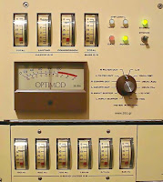
In 1975 Orban Associates introduced "Optimod-FM." This unit combined compressor, limiter, high-frequency limiter, clipper, 15kHz low-pass filters, and stereo multiplex encoder into one box. This greatly reduced the possibility of misadjustment of the processing chain. The unit's 15kHz low-pass filters were non-linear filters without significant overshoot, and therefore permitted higher average modulation by comparison to the linear low-pass filters used in the stand-alone stereo encoders of the time.
In 1977 Orban Associates introduced "Optimod-AM." This unit contained a high-slope receiver equalizer to pre-compensate for the highly rolled-off radios of the time, and also included an 11kHz low-pass filter to ensure that the unit complied with the occupied bandwidth requirements of the 1978 FCC Rules. It also introduced the distortion-canceling clipper, which substantially reduced difference-frequency intermodulation distortion caused by clipping.
In the late 1970s, Circuit Research Laboratories introduced a processing system for AM whose most important novel features were a phase rotator [the Kahn "Symmetra-Peak" being a fore-runner] prior to processing (to make voice more symmetrical, reducing clipping distortion), and a subsonic equalizer after final peak clipping to pre-distort the output waveform of the processor to compensate for low-frequency tilt in the plate-modulated transmitters of the time. Compensating for this waveform tilt enabled the better transmitters to be substantially louder by eliminating a factor that would otherwise increase the peak-to-average ratio of the modulation. Although intuitively inobvious, using a phase rotator to purposely eliminate the asymmetry in voice proved to be far more effective than the older "polarity follower" [Pacific Recorders AM "Modulimiter"] circuit. The older circuit preserved any natural waveform asymmetry and switched its output polarity such that the side of the waveform with the higher peak level modulates the carrier in the positive direction.
In the late 1970s, a number of manufacturers made "composite clippers" designed to be placed between the output of the stereo encoder and the input of the transmitter. These controlled the peak modulation of the composite stereo signal unambiguously at the expense of introducing harmonic and intermodulation distortion throughout the stereo baseband. Many "hit-format" broadcasters thought that the increased loudness achieved by these devices justified compromising the spectral purity of the baseband. Eventually, the FCC judged these devices to be in violation of the FCC Rules of the time if they caused the instantaneous 19kHz stereo pilot tone injection to be less than 8% modulation. In essence, this meant that the pilot could not be clipped and must be injected after the clipper. In 1982, Modulation Sciences introduced a composite processor that did this, thereby performing to the letter of the FCC Rules.
In 1982, Orban Associates introduced the "Hilbert-Transform Clipper" as part of its Optimod-TV processor for stereo television. The "Hilbert-Transform Clipper" was later adapted for use in shortwave as well.
In general, transmission audio processing in the 1980s refined and built upon the revolutionary developments of the 1970s without introducing any radical novelties. Each manufacturer, for example, has a proprietary technique for producing non-linear overshoot-free low-pass filters for FM and television applications. Several manufacturers (including Inovonics and Circuit Research Laboratories) introduced programmable processors whose subjective setup controls can be changed by remote control to match the programming of the moment.
In the 1990s, the field must be considered "mature." As in every other area of audio, digital signal processing (DSP) is likely to eventually supplant analog circuitry. As of this writing, Orban, CRL, Valley International, Gentner Electronics, and Audio Animation have introduced transmission processors in which all processing is done in the digital domain. [The Valley, Gentner, and Audio Animation units are no longer manufactured.] If properly designed, such a processor can be readily reconfigured in milliseconds to change almost any aspect of its topology, such as the number of bands in its multi-band compressor. Subjective setup control settings can be stored and later recalled by local clock, remote control, or computer to daypart processing. The processor can readily generate test and signalling tones, facilitating tests of the transmission system and the generation of EAS alert tones.
In a digital processor, achieving sound quality equal to or better than its analog counterparts requires a marriage of art and mathematical design more rigorous than anything in the genesis of its analog ancestors. Many common analog processing functions (such as clipping) are much more difficult to do competently in the digital domain. However, digital also presents the opportunity to do things unachievable in analog, and digital's overwhelming advantages will ultimately manifest themselves as clearly here as they have elsewhere in the audio processing arena.
Robert Orban
From www.261.gr
Robert Orban
Chief Engineer. Orban/CRL

In the early days of broadcasting, the primary purpose of transmission audio processing was to protect the AM transmitters of the time from damage due to modulator overload. Simple peak limiters using variable-mu tubes in a push-pull configuration were employed. Because the gain-control signal was, in essence, mixed with the audio signal, these early vacuum-tube devices required careful balancing to cancel "thumps" representing feedthrough of the gain-control signal into the audio. Dynamic range control was effected through careful manual gain-riding -- in classical music broadcasts, the "compressor" was a skilled operator reading the musical score and using it to anticipate the required level adjustments. To this day, no one has invented a more subtle or effective method of compression!
Later, simple compressors were placed upstream from the limiters in situations where the budget did not permit skilled manual gain-riding. These compressors were not gated and could exaggerate noise objectionably.
In the Region 2 countries, 75µs pre-emphasis is used in FM and television sound transmission. This pre-emphasis is up 17dB at 15kHz and can cause severe over-modulation if its effects are not controlled. The obvious solution - placing a wide-band peak limiter after the pre-emphasis filter - proved unsatisfactory because high-frequency overloads would cause severe spectral gain intermodulation: cymbal crashes would cause the sound to literally collapse. The Fairchild "Conax" (originally designed for disk cutting) was often used to ameliorate the problem. This device divided the audio into two bands with a 1kHz crossover and applied pre-emphasis, clipping, and high-pass filtering to the upper band. The high-pass filter reduced the difference-frequency intermodulation caused by the clipper, yielding reasonably acceptable sound.
"Modern audio processing" could be said to derive from the work of the design team at CBS Laboratories in the early 1960s. Their "Audimax" (mispronounced by generations of engineers as "audiomax"!) was a gated wideband compressor that successfully eliminated the noise-breathing problem of earlier compressors. The "Volumax" was a clipper preceded by a limiter with a moderate attack time. The moderate attack time prevented the unit from punching holes in the program, while the clipper controlled the peaks that the preceding limiter did not catch. The "FM Volumax" introduced a high-frequency limiter to control overload due to the pre-emphasis curve. This high-frequency limiter was a program-controlled 6dB/octave shelving filter placed between the limiter and clipper. Once again, a moderate attack time was used and the overshoots were controlled by a final clipper. The "Dynamic Presence Equalizer" measured the ratio of midrange energy to wideband program energy and applied midrange equalization as necessary to correct the midrange spectral balance of the program.
In the early 1970s, Dorrough Electronics introduced the "Discriminate Audio Processor" ("DAP"). There were versions for AM and FM. The DAP divided the audio spectrum into three bands with gentle crossover slopes and compressed each band independently. The bands were recombined and applied to a clipper with a very "soft" transfer characteristic. The DAP greatly reduced spectral gain intermodulation by comparison to its wideband predecessors. Additionally, many engineers adjusted the three bands for different gains, using the device as a dynamic program equalizer as well.
In 1975 Orban Associates introduced "Optimod-FM." This unit combined compressor, limiter, high-frequency limiter, clipper, 15kHz low-pass filters, and stereo multiplex encoder into one box. This greatly reduced the possibility of misadjustment of the processing chain. The unit's 15kHz low-pass filters were non-linear filters without significant overshoot, and therefore permitted higher average modulation by comparison to the linear low-pass filters used in the stand-alone stereo encoders of the time.
In 1977 Orban Associates introduced "Optimod-AM." This unit contained a high-slope receiver equalizer to pre-compensate for the highly rolled-off radios of the time, and also included an 11kHz low-pass filter to ensure that the unit complied with the occupied bandwidth requirements of the 1978 FCC Rules. It also introduced the distortion-canceling clipper, which substantially reduced difference-frequency intermodulation distortion caused by clipping.
In the late 1970s, Circuit Research Laboratories introduced a processing system for AM whose most important novel features were a phase rotator [the Kahn "Symmetra-Peak" being a fore-runner] prior to processing (to make voice more symmetrical, reducing clipping distortion), and a subsonic equalizer after final peak clipping to pre-distort the output waveform of the processor to compensate for low-frequency tilt in the plate-modulated transmitters of the time. Compensating for this waveform tilt enabled the better transmitters to be substantially louder by eliminating a factor that would otherwise increase the peak-to-average ratio of the modulation. Although intuitively inobvious, using a phase rotator to purposely eliminate the asymmetry in voice proved to be far more effective than the older "polarity follower" [Pacific Recorders AM "Modulimiter"] circuit. The older circuit preserved any natural waveform asymmetry and switched its output polarity such that the side of the waveform with the higher peak level modulates the carrier in the positive direction.
In the late 1970s, a number of manufacturers made "composite clippers" designed to be placed between the output of the stereo encoder and the input of the transmitter. These controlled the peak modulation of the composite stereo signal unambiguously at the expense of introducing harmonic and intermodulation distortion throughout the stereo baseband. Many "hit-format" broadcasters thought that the increased loudness achieved by these devices justified compromising the spectral purity of the baseband. Eventually, the FCC judged these devices to be in violation of the FCC Rules of the time if they caused the instantaneous 19kHz stereo pilot tone injection to be less than 8% modulation. In essence, this meant that the pilot could not be clipped and must be injected after the clipper. In 1982, Modulation Sciences introduced a composite processor that did this, thereby performing to the letter of the FCC Rules.
In 1982, Orban Associates introduced the "Hilbert-Transform Clipper" as part of its Optimod-TV processor for stereo television. The "Hilbert-Transform Clipper" was later adapted for use in shortwave as well.
In general, transmission audio processing in the 1980s refined and built upon the revolutionary developments of the 1970s without introducing any radical novelties. Each manufacturer, for example, has a proprietary technique for producing non-linear overshoot-free low-pass filters for FM and television applications. Several manufacturers (including Inovonics and Circuit Research Laboratories) introduced programmable processors whose subjective setup controls can be changed by remote control to match the programming of the moment.
In the 1990s, the field must be considered "mature." As in every other area of audio, digital signal processing (DSP) is likely to eventually supplant analog circuitry. As of this writing, Orban, CRL, Valley International, Gentner Electronics, and Audio Animation have introduced transmission processors in which all processing is done in the digital domain. [The Valley, Gentner, and Audio Animation units are no longer manufactured.] If properly designed, such a processor can be readily reconfigured in milliseconds to change almost any aspect of its topology, such as the number of bands in its multi-band compressor. Subjective setup control settings can be stored and later recalled by local clock, remote control, or computer to daypart processing. The processor can readily generate test and signalling tones, facilitating tests of the transmission system and the generation of EAS alert tones.
In a digital processor, achieving sound quality equal to or better than its analog counterparts requires a marriage of art and mathematical design more rigorous than anything in the genesis of its analog ancestors. Many common analog processing functions (such as clipping) are much more difficult to do competently in the digital domain. However, digital also presents the opportunity to do things unachievable in analog, and digital's overwhelming advantages will ultimately manifest themselves as clearly here as they have elsewhere in the audio processing arena.
Robert Orban
From www.261.gr
FM Telephone Bug
FOR EDUCATIONAL PURPOSE ONLY! WE ACCEPT NO LIABILITIES FOR WHAT YOU MAY DO WITH THE CONTENT OF THIS ARTICLE.
From: http://www.aaroncake.net/circuits/phonebug.asp
Here is a simple transmitter that when connected to a phone line, will transmit anything on that line (execpt the dial tone) to any FM radio. The frequency can be tuned from 88 to about 94Mhz and the range is about 200 feet. It is extremely easy to build and is therefore a good, useful beginner project.
Schematic

Parts
Part----Total Qty.-Description
R1---------------1----180 Ohm 1/4 W Resistor
R2---------------1----12K 1/4 W Resistor
C1---------------1----330pF Capacitor
C2---------------1----12pF Capacitor
C3---------------1----471pF Capacitor
C4---------------1----22pF Capacitor
Q1---------------1----2SA933 Transistor
D1, D2, D3, D4---4----1SS119 Silicon Diode
D5---------------1----Red LED
S1---------------1----SPDT Switch
L1---------------1----Tuning Coil
MISC-----------1----Wire, Circuit Board
Notes
L1 is 7 turns of 22 AWG wire wound on a 9/64 drill bit. You may need to experiment with the number of turns.
By stretching and compressing the coils of L1, you can change the frequency of the transmitter. The min frequency is about 88 Mhz, while the max frequency is around 94 Mhz.
The green wire from the phone line goes to IN1. The red wire from the phone line goes to IN2. The green wire from OUT1 goes to the phone(s), as well as the red wire from OUT2.
The antenna is a piece of thin (22 AWG) wire about 5 inches long.
All capacitors are rated for 250V or greater.
The transmitter is powered by the phone line and is on only when the phone is in use. S1 can be used to turn the transmitter off if it is not needed.
If you have problems with the LED burning out, then add a 300 ohm 1/4W resistor in series with it.
Electrical playback of cylinders

Since the early days, sound recording has been far superior to sound reproduction. Early apparatus could reproduce only a fraction of the frequencies recorded on the cylinders (from 300 to 3000 Hz with the best ones). Acoustical reproduction systems were so limited in the higher and lower end of the spectrum that they could not even reproduce a female voice correctly - not to mention piano music. Only electrical playback allows us to hear all that has been recorded on a cylinder, and we are often surprised. All cylinders are "hill and dale" vertically cut, like Diamond discs . So we will use a Shure SC35C cartridge wired for vertical response.
--------------------------------------------------------------------------------
Which phonograph to use
For playing old discs we can use a modern turntable with an electric motor, but unfortunately there is no cylinder player equipped with an electric motor. The first solution would be to build a machine specifically for this use: it is possible, but it is a matter of precision mechanics and high skill in that field is required. Just take a look at the work of a few especially talented amateurs on an extraordinary site dedicated exclusively to modern cylinder phonographs You can find inspiration there if you feel you are capable of getting into such a project. The other solution, the one I have adopted, is to use the works of an old phonograph. For the purist, it is a less satisfactory solution, but it has the advantage of being feasible by a moderately skilled amateur, and for a very modest price too. This is the interest of the "Fradetophone" (unregistered trade mark !)described here.
A bare mechanism without the wood case can still be found easily and cheaply, and with a bit of work it can serve as a base for our electrical player. But do make sure it is a model equipped with a feedscrew that permits the reproducer to track the groove. So you can exclude the Pathé O and Puck types, whose mechanism is too weak anyway for serious use. Another must is that the mandrel be of the standard type, which allows for standard cylinders and Salon (Intermediate Pathé) cylinders with an adaptor. The Pathé Chanteclair will only take Salon cylinders and the Phénix will only take Phénix cylinders (practically impossible to find and with a very special diameter). The Edisons will only take standard cylinders and do not allow for the use of an adaptor. The ideal is to find a Pathé No 1 (a fairly common model) which has a pretty robust mechanism, with a feedscrew and which takes the two common diameters of cylinders. Of course, the large Concert cylinders will not be playable on it, but as there is a very slight chance for you to have any, I just skipped the question.
--------------------------------------------------------------------------------
Mechanical or electrical motor?
The easy solution is to keep the original mechanical motor... if it works - provided it is not too noisy. Most small models actually produce a terrible noise which is picked up by the cartridge - and amplified! This mechanical noise somtimes spreads over the entire useful spectrum of frequencies and will thus be impossible to eliminate. If the original mechanism does not work, so much the better. Just take it out (but don’t throw it away, there may be parts there to recover to repair a collector’s phonograph). A good starting point is to find a quiet electric motor, which is a lot more convenient. I personally use a DUAL Pick-up motor for 78’s of the 1930’s. Those can still be found easily at flea markets for a modest price. They are very interesting, for they are strong, fairly quiet and above all they have a centrifugal three-weight governor that allows for perfect speed control. We will only remove the turntable spindle and use the helical gear (after soldering a brass sleeve onto it) as the primary pulley. Make a leather belt to connect this pulley to the mandrel pulley. Then put your ingenuity to work and mount the motor giving it some clearance so you can adjust the tension of the belt. I recommend you to spray the inside of the belt with a special compound that will help avoid slippage and power loss. At last check if the mandrel is heavy enough to work as a flywheel that will absorb small speed variations . If it is not so, then open it. It is hollow and the lid can be easily removed. Melt some lead (or tin solder) into it to obtain a thick and even layer, without of course obstructing the hole for the central axle. The mass of lead should be perfectly balanced in order to function as a flywheel.
--------------------------------------------------------------------------------
How to fix the electrical pick-up arm
The Pathé No 1 phonographs are provided with the"Orpheus" system, which means the reproducer and horn move together along the cylinder. The reproducer should have some vertical and lateral mobility while always staying level. We will keep this excellent "Orpheus" system and simply replace the reproducer-horn unit by a modern arm fitted with a magnetic cartridge. So we must take a complete arm with its pivot and counterweight from a modern turntable. The problem will be to find a straight arm (not an S-shaped one) and fix it on the antique cylinder phonograph. The image above shows the system I use, but it can certainly be improved on. The counterweight permits adjustment of pressure according to the cylinder to be played. Normally 3 grams will be quite enough except if the cylinder is a little excentric, in which case you may increase pressure to 5 grams to keep the stylus from taking off at every revolution.
--------------------------------------------------------------------------------
Which stylus to use
The original "sapphires" were in most cases small glass balls. If you have an original one, you may try and glue it to a used microgroove stylus bar. You will need a watch-maker’s magnifying glass, a pair of very fine tweezers, some cyanolite glue - and the patience of an angel. But it can be done. A Shure cartridge fitted with such a ”sapphire” will perform well, especially with brown wax cylinders. In difficult cases, with cracked or badly worn cylinders, only the glass ball will be able to jump over the cracks and keep tracking the groove. But for black cylinders, which are made of a much harder material, the glass ball should not be used. It is more advisable to use a practically everlasting diamond stylus, which will reproduce more treble. The English manufacturer Expert Stylus makes 7 mil diamond styli for Shure cartridges, especially intended for use with standard 2 minute cylinders.
--------------------------------------------------------------------------------
Adjusting the speed
Cylinders normally spin at 160 rpm. This is the rule for black moulded cylinders. Brown cylinders do not always respect this speed and many of them run at slower and very different speeds. There is no other option than to set the speed by ear. All mechanical phonographs have a speed adjustment that allows us a wide range of speeds. We are now going to attach a stroboscope for 160 rpm to the end of the mandrel and stick with that speed in most cases. If the sound seems unlikely at that speed, reduce speed until it sounds right. Most certainly very subjective, but there is no other way...
--------------------------------------------------------------------------------
Electrical connections
The signal produced by the cartridge is very weak and very susceptible to intereference. Therefore good shielded cables are essential. Some "shielded" cables for HiFi are real sieves and so practically useless. Choose only cables with a densely woven braid that surrounds the central conductor completely. This is the only way to avoid undesired hiss, hum and crackle. Connect the two RCA plugs into the phono input of your amplifier, the only input that can be used with this kind of reproducer. Even so we must know one important thing: all phono inputs on all contemporary amplifiers include a filter called RIAA, which raises the low frequencies and lower the high, correcting the frequency curve of the microgroove discs. Older phonograms (discs and cylinders) have not been recorded according to this curve. We must then use a special preamplifier or a graphic equaliser to cancel this RIAA correction. Anyway, when playing cylinders, electric reproduction will give a terrible mechanical noise in the low register, and at the high end a no less terrible surface noise. It is absolutely necessary to filter out all useless frequencies and keep only the useful signal. On a cylinder there is nothing below 300 Hz neither above 4000 Hz, so you can filter drastically without regrets. Then what you have is the signal in all its - relative - clarity. And if you have no filters or equaliser, set the bass and treble to minimum. It is better than nothing and it permits listening to your old cylinders in relative comfort.
But in order to make high quality transfer of cylinders, this is very insufficient, and in that field, computerised sound processing is a must. That will be the subject of the following chapter
Thanks to Christer Hamp from Sweden for translating this page
Last updated January 18 th 2000
Copyright Jean-Luc Fradet / 1998 -2000
An introduction to low power FM transmission (or pirate radio basics...) part 4
How far will my signal go?
In theory, the range of a transmitted electomagnetic wave is infinite regardless of power used,
it continues until it encounters an obstruction. more power helps to overcome any obstructions.
but is limited by how far the transmitting antenna can effectively see!
If there is a clear line of sight between the transmitter and the receiver (nothing in the way)it should be possible to receive the signal, the curvature of the earth can soon become a limiting factor
Sources of interference or other stations operating on the same frequency.
Basically the same as people shouting over each other in a room,
the loudest one(s) get heard, and its possible to seperate the sounds of the loudest people who
have a different pitch(frequency) voice
and remember: shouting is not polite, especially in public
Transmission power (Effective Radiated Power).
You could expect a 10w station to have around a 20 mile range with a reasonable antenna
http://www.veronica.co.uk/range.htm

having your aerial as high as possible.
Maybe consider using balloons or kites to lift your antenna?
Here is some information on the subject:
Prior safety warnings:
1. Give a wide berth to power lines (unless you want to look like a sausage roll).
2. Be very careful about static (unless you want to cross the rubicon).
3. Pay attention to air traffic (unless you want to pay through the nose).
http://www.hard-core-dx.com/nordicdx/antenna/special/baloon.html
http://www.qsl.net/g4vgo/balloon_antennas.htm
http://www.chem.hawaii.edu/uham/lift.html
http://www.helikites.com/skyhook/aad.html
Want to go higher?
That could be a stratosferic solution: http://www.eoss.org/pubs/faqloon.htm
http://www.economist.com/science/tq/displayStory.cfm?story_id=3423026
Want to go even higher?
Where blue turns black before it comes back:
http://bordelon.net/freespace/radioflier-1/default.html
When you get so high, you may start thinking satellite
History of AMSAT
AMSAT Documents for New Satellite Users
Sounds from the First AMSAT Satellites
OSCAR project - Orbital Satellite Carrying Amateur Radio
Maybe these bakery sponsered guys will help you lauch yours??:
http://www.jpaerospace.com
Give us a slot on your program then?!:)
Don't forget - a good mast will help!
Been away from Mother England for too long? In need of gravy granules, daddies favourite and ash browns?
Well that should be alright! Maybe you miss London's highlights: promiscuity, DLR and pollution. In that case the London Pirate Listening Station may be of temporary salvation: http://scanner.irational.org/
Saturday, 13 December 2008
An introduction to low power FM transmission (or pirate radio basics...) part 1

Important notice: this information is for educational purpose only.
We hope to make you conversant with the main principles and methods of fm propagation.
If you intend to "break-in" the fm band, don't read any further! 
"Before you commit to your first broadcast - it would be advisable to have an attorney
available, who is sympathetic to the cause."
"...It's fairly easy for the DTI to track a transmission back to its source, by triangulating the signal."
"In court dress neatly and be polite to the bastard (magistrate) and the filth"
Before we go any further please have a look at: http://www.c6.org/archive/radio/pirate-fm.htm
In the next articles, we'll have a closer look at:
- What equipment do I need (part2)?
- What frequency should I choose(part3)?
- How far will my signal go (part4)?
- Considerations on dynamics (part 5).
Hope it will be of some inspiration for those interested in FM propagation.
Happy reading!
An introduction to low power FM transmission (or pirate radio basics...) part 3
What frequency should i choose?
Choose a frequency nobody is else is using, simple as that!
Most importantly!
Make sure you dont interfere with other (especially officially valid) radio users
Before you transmit, (days before even!) roam the area you will cover with a good radio, make sure nobody is using your desired frequency.Find a quiet part of the spectrum, make sure your signal does not break-in(bleed) onto an adjacent used frequency.
Find out how your rig behaves at full power (cold, warm and hot) in an isolated area, is there frequency any drift?
Get an SWR meter (and use it!) http://www.smeter.net/feeding/swrmeter.php
Finally, read all you can about the subject. And note regional differences such as pre-emphasis
Radio terms and abbreviations http://www.dxing.com/radioterms.htmARRL abreviations http://www2.arrl.org/qst/aguide/Abbrev_AWE.pdf
If your not creating a nuisance - then you may just get away with it!
Happy raving :)
An introduction to low power FM transmission (or pirate radio basics...) part 2
What equipment do I need?
The portable set up:
This is a quick review on what you need. Make sure to browse the internet for further detailed information.
Tape player
We advice you to go for a reliable professional cassette player
with a good rca or xlr output.
like the Sony tcd5 pro2
A Sony Pressman may do the trick as well.
"Townies iPod and MP3 players won't give you any satisfaction!"
Preamp

Assume every portable transmitter you can find is not intended to compete with professional broadcasters, a preamplifier will be handy to strengthen your signal. We are using a Nagra IV.2 for this. The main inconvenient is its weight. Walking in fields to the broadcasting location or climbing up stairs with the bastard on your back will make you consider getting its hard to find but well efficient pocket-sized little sister: the Nagra SN.
the Nagra SN:
You may also skip the Nagras and go for a home made portable console.
Here is a starting point then:
These people know the ropes on Telefunken, Siemens, EMT, Neve equipment.
http://www.danalexanderaudio.com/
http://www.marquetteaudiolabs.com/
Transmitter
This is the core of your system. May we suggest you to make a search on the interweb for "portable fm transmitter"?
We don't want to put you on the screw too much ladies but don't make us plough the sands. Does it mean anything??? ... Hahaha (from a book of English idioms) Look for something you like with similar specifications to a Bext P10.
Bandpass filter
This is all about harmonics (multiples of your tranmissions frequency).
Let's say you're broadcasting on nine-o-nine Mhz, your aerial will send harmonics of this frequency as well. In that case 181.8, 363.6, 727.2, etc… Mhz, which are not inside the 87-108 fm band anymore.
You'll be a pain in the neck for emergency services (police, ambulances, firemen) without even noticing it… which means they'll put the DTI on your case without any delay. You may loose half a dB using it, although the loss of that dB might save somebodies life!
or help somebody get away :)
Power supply
Your power requirements will depend on your rig. 12v is the normal requirement, so a car battery is suitable (without the car running! or use a regulation circuit). Car emergancy starters are good (dont be tempted by the crap strobes on it though). Deep discharge battery will last longer and give better performance, electric wheelchairs use these, so they are easy pickings!:)
The more you spend, the more power you get, also it's easier to carry.
cheaper > more expensive: lead acid, Gel Lead acid, NiCads, Lithium Based batteries.
The more efficient (and expensive) the battery technology is, can also mean it's more difficult (expensive) to charge safely.
If you are going to be located in one place for some time, you may be able to use the forces of nature to keep you powered up i.e., solar or wind can trickle charge your batteries in time for your broadcasts.
Here's some links:
http://electronics.howstuffworks.com/battery.htm
http://www.vonwentzel.net/Battery/00.Glossary/
http://www.batteryweb.com/
http://www.exideworld.com/
http://www.mdsbattery.co.uk/defaultuk.asp
http://www.homepower.com/
http://www.americansolarchallenge.org/event/asc2005/
http://www.rain.org/~philfear/how2solar.html
http://home.earthlink.net/~fradella/green.htm
Mast
Unless you can find a location atop of a high building, a mast is a must!
Go for an air-operated 10 to 12 meters high mast which is the best value for weight, strenghtness and minimum retracted height.
http://www.alphalink.com.au/~gfs/Clark/clarkp30.htm
You can also go DIY with aluminum tubes and guy wires.
Antenna
The other key part of your radio station. It is similar to a loud speaker in a stereo system.
Again, we advice you to have a deep look on the internet on different models and manufacturers.
http://www.ac6v.com/antprojects.htm
Cable
It brings the signal from your transmitter to the aerial. Keep it as short as possible.
Any unnecessary meter will weaken your signal and then the signal/noise ratio.
To get it, have a quick look at some electricity basics here.
http://hyperphysics.phy-astr.gsu.edu/hbase/electric/ohmlaw.html
Quality RG213 cable is a good choice.
Other
Don't go out for a broadcast without appropriate clothing! It's too late to think about your missing top when you're on air. Double check batteries and that you take any tools you need for mast erection, rope, gloves and flashlight. A sweety may be welcome and a glass of Merlot as well! You may be in a rude environment; it doesn't mean you have to get rid of pleasures of life.
Subscribe to:
Comments (Atom)


